Piping Isometric Drawing Online — No CAD Seat, No Install
Piping isometric drawing online: route a line in a live 3D view, drag nodes to edit the geometry, and get dimensioned iso sheets — feet-inches-sixteenths callouts, stress-model node numbers, weld balloons, and a filled title block. Export a seven-tab Excel workbook, sheet-formatted PDF, DXF, or CSV. No CAD seat, no install. It is not production CAD — the limits are stated plainly below.
Content last reviewed · page regenerated 2026-09-13 at build.
What it does
You model the run once, in 3D; the tool draws the iso. The model is English units — inches internally, every displayed dimension in feet-inches-sixteenths, the way isos are read in the field.
Modeling
- 3D-to-2D: live 3D view with drag-to-edit geometry; the 2D isometric sheet is generated from the same model, so the drawing and the dimensions never disagree.
- 45° routing: besides one-click axis routing, per-axis ΔN/S · ΔE/W · ΔUP/DN entry extrudes a compound-direction run — the way a stress model takes element deltas — and each direction change inserts the B16.9 elbow the actual bend angle calls for, 45° or 90°.
- Component library: ASME B16.9 elbows (90° and 45°, LR or 3D radius), tees, caps, concentric and eccentric reducers, weld-neck and slip-on flanges, twelve valve types (gate, globe, check, ball, butterfly, plug, needle, diaphragm, three-way, Y-strainer, control, relief), equipment tie-ins drawn with recognizable symbols (pump, vessel, heat exchanger, nozzle), and supports — rod hangers, spring hangers, guides, anchors, shoes, and trunnions — with MSS SP-58 type tags where applicable.
- Line spec: NPS 1/2 in through 16 in, Schedules 10S/40/80 (160 through NPS 8), carbon or stainless steel, weights from the ASME B36.10/B36.19 tables, and a user-adjustable weld root-gap allowance (0.125 in default).
- Node numbering: stress-analysis style — nodes numbered in routing order at a configurable increment (default 5), so a check iso can carry the same node scheme as the flexibility model.
- Welds: sequential balloon numbering, BW/FW joint classification, default NDE percentage by B31.3 fluid-service category (normal 5%, Category D 0%, severe cyclic 100%, Category M 100%), and hydro-test pressure from the 1.5 × P × St/S ratio.
- Supports: placed at a node or mid-segment by distance from the segment start; tags auto-generate per support type, and hanger-assembly data imported from the support-selection tool stays with the project.
Sheets and title block
- Letter (8.5 × 11 in) and 11 × 17 in Tabloid landscape templates. A drawing too large to stay legible on one sheet auto-paginates across sheets, with continuation marks at the match points.
- Title block editor: project and job fields, service type, design pressure and temperature, NDE method, revision history, reference drawings, and shop/field labor rates and material costs — the rates feed the quote estimate.
Exports
- Excel, 7 tabs: BOM (pipe and fittings aggregated by size, material, and schedule), cut list (spool take-outs with root gaps per B16.9), weld TQC (balloon-numbered joints with WPS/NDE columns), supports (E/N/EL coordinates plus imported hanger assemblies), quote (labor and material from the title-block rates), datasheet (B31.3 defaults), and revisions.
- PDF: sheet-formatted drawing with on-sheet BOM, feet-inches-sixteenths dimensions, and weld flow arrows; dimension, weld-balloon, and node-number overlays toggle on or off, and sheet breaks carry continuation marks.
- DXF: hand-written plain-ASCII DXF, so the linework opens in CAD.
- CSV: job/title/service summary, BOM (item/SKEY/qty/weight), cut list (spool/NPS/centre/take-out/cut), and supports (tag/type/SKEY/MSS/location).
Drawing and editing run entirely in your browser. The model leaves your device only when you choose cloud save or share; local work stays local.
Who it's for
Built for the drawings that never justify a CAD seat:
- Field and site engineers. Capture a tie-in, a reroute, or an as-built on whatever machine is in front of you. Browser only — no install, no license checkout, nothing to request from IT.
- Small fab shops. Go from sketch to a cut list with take-outs and root gaps, a balloon-numbered weld map, and a BOM aggregated by size, material, and schedule — without buying a drafting seat for a few spools a month.
- Checkers and leads running markup rounds. Cloud share issues a read-only link, so the reviewer sees the current drawing instead of a screenshot, and the revision history lives in the title block where it belongs.
- Stress engineers. Node numbers follow stress-analysis convention — routing order, configurable increment — so the iso and the flexibility model can share one numbering scheme.
It is not aimed at production drawing offices. If your project extracts isos from a spec-driven 3D model, keep that workflow — this tool covers the sketches around it.
Where it sits next to desktop CAD
Plainly: this is not production CAD, and it does not replace Plant 3D or AutoCAD-based iso workflows. There is no spec-driven routing, no clash checking, and no drawing database. What it replaces is the pencil iso on graph paper — with a model that dimensions itself and exports a BOM.
| This tool (browser) | Desktop CAD iso add-ons | |
|---|---|---|
| Install | None — runs in the browser | CAD platform seat plus add-on, per workstation |
| Model basis | Hand-routed model with drag-to-edit 3D geometry | Spec-driven 3D plant model |
| Drawing standards | Fixed Letter / 11 × 17 templates, auto-pagination | Project borders, layers, full drafting control |
| Deliverables | Sheet PDF, 7-tab Excel (BOM / cut list / weld map), DXF, CSV | Production iso packages tied to the project CAD database |
| Fits | Field sketches, tie-ins, small spool jobs, check prints | Full project deliverable sets |
The DXF export is the bridge between the two: plain ASCII DXF that CAD opens, so a field sketch becomes linework instead of a redraw.
A typical run: sketch to sheets
The flow mirrors how you would mark up a paper iso, in order:
- 1 — Route the line. Extrude segments in the 3D view and drag nodes until the geometry is right. Set NPS, schedule, and material; dimensions read out in feet-inches-sixteenths as you go, and bends auto-insert a B16.9 elbow — 45° or 90°, read from the actual bend angle — at the radius you selected (LR or 3D).
- 2 — Place components. Tees, reducers, flanges, valves, caps, equipment tie-ins, and supports from the library. Supports land at the current node or at a ft-in distance along the last run, and tags generate automatically per type.
- 3 — Number the nodes. One setting — the increment, default 5. Numbers assign in routing order, stress-analysis style, and appear at each node on the drawing.
- 4 — Fill the title block. Project, job, service, design pressure and temperature, NDE method, revision rows, reference drawings — plus labor rates and material costs if you want the Quote tab of the workbook populated.
- 5 — Let it break sheets. Pick Letter or 11 × 17 landscape. A run too long for one legible sheet paginates automatically, with continuation marks tying the sheets together.
- 6 — Export. Excel workbook to the shop, sheet PDF for review and markup, DXF to CAD, CSV to whatever else consumes it.
Working limits, stated plainly: undo is one step deep, and reset returns to a blank model.
What's free and what needs Pro
The drawing tool itself is free: open it, model, dimension, number nodes, fill the title block, and take the CSV — no account required, nothing to cancel. The premium outputs sit on the Ultimate tier:
- Free — $0: full modeling and editing, on-screen iso with dimension / weld-balloon / node-number overlays, and CSV export (BOM, cut list, supports).
- Pro — $2.99/month or $29/year: adds .pcp project files (save, reopen, share) and the report and batch workflow on the calculator side of the app.
- Pro Plus — $7.99/month or $79/year: adds PiperHGR (PT&P spring sizing / 3D model / datasheet), which is where the hanger assemblies the iso can import come from, plus PiperNOZ nozzle loading and PiperFLG bolted-flange analysis.
- Ultimate — $14.99/month or $149/year: adds the ISO premium output — the 7-tab Excel workbook, sheet-formatted PDF, DXF, and cloud save and share with read-only links — plus PiperFEA (nozzle/shell FEA, commissioning — validation status published) and PiperSTR.
One caution on PiperFEA, since it shares the tier: it is a screening and check aid benchmarked against commercial FEA reference cases and still in commissioning — not a replacement for a full B31.3 flexibility analysis in CAESAR II or AutoPIPE.
The full feature matrix and billing FAQ are at /pricing/.
Demo video
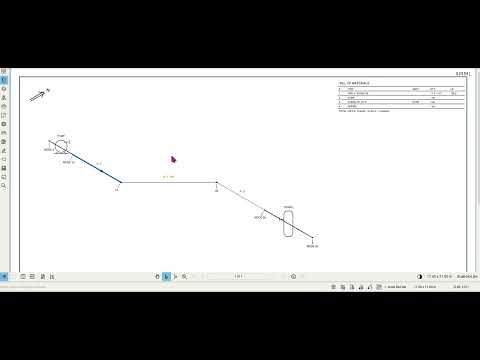 ▶
PiperISO - ASME B31.1 Piping Isometric Drawing Generator - New Features & Updates (1:47) — The current feature pass: the ASME B16.9 component library with long-radius and 3D-radius elbows, twelve valve types, equipment tie-ins and MSS SP-58-tagged supports, drag-to-edit routing, and the iso sheet generated from the model with routing-order node numbers and weld balloons. Watch on YouTube.
▶
PiperISO - ASME B31.1 Piping Isometric Drawing Generator - New Features & Updates (1:47) — The current feature pass: the ASME B16.9 component library with long-radius and 3D-radius elbows, twelve valve types, equipment tie-ins and MSS SP-58-tagged supports, drag-to-edit routing, and the iso sheet generated from the model with routing-order node numbers and weld balloons. Watch on YouTube.
 ▶
ASME B31.3 Piping Isometric Drawing Generator - 3D Model to Print-Ready ISO Sheet (2:40) — The full pass in one recording: modeling from the B16.9 component library, node numbering in routing order, weld balloons with B31.3 NDE percentages, the title block, and the sheet output with its export set. Watch on YouTube.
▶
ASME B31.3 Piping Isometric Drawing Generator - 3D Model to Print-Ready ISO Sheet (2:40) — The full pass in one recording: modeling from the B16.9 component library, node numbering in routing order, weld balloons with B31.3 NDE percentages, the title block, and the sheet output with its export set. Watch on YouTube.
Open the tool
Open Piping ISO Drawing — it loads in the tab you are reading this in; no download, no signup. Draw the line in front of you, and if the free CSV covers the need, that is the whole workflow. When you want the Excel workbook, the sheet PDF, DXF, or a share link for a check round, Ultimate is $14.99/month or $149/year.
For the numbers the drawing does not produce, the calculators are free: B31.3 wall thickness for the pressure-design thickness behind the schedule you picked, thermal growth for movement between anchors, and expansion loop sizing when the routing needs flexibility.
FAQ
How does dimensioning work — do I place dimensions by hand?
No, and that is a deliberate design decision rather than a missing feature. Dimensions come from the model geometry: the model is stored in inches and every displayed dimension renders as feet-inches-sixteenths, on screen and on the PDF sheet. A hand-placed dimension can disagree with the geometry it labels — that is how a sketch ships with a 10'-6" callout on a 10'-5" run — while a model-derived dimension cannot lie without the model itself being wrong, which the drawing makes visible. Length entry accepts 10'-6", 126, or 10.5' and normalizes all three to the same stored inches. Dimension, weld-balloon, and node-number overlays each toggle independently, so a check print can show exactly the layer you are reviewing: dims only for the fitter, welds only for the TQC walk, nodes only when tying the sketch to a stress model.
What export formats are available, and which are paid?
CSV export — job summary, BOM, cut list, and supports as separate files — is free, permanently, with no account. Ultimate at $14.99/month or $149/year adds the outputs built for handing off: a 7-tab Excel workbook (BOM, cut list, weld TQC, supports, quote, datasheet, revisions), the sheet-formatted PDF with title block, DXF, and cloud save/share. Two details worth knowing before you buy. The DXF is plain ASCII, written to import cleanly into AutoCAD or any DXF reader, and because it is text it can be inspected or post-processed by a script — no binary vendor format. And the Excel workbook's quote tab is set up so a fab shop can price directly off the same file the fitter cuts from, which is the point of a single-source export: one model, one set of numbers, every downstream document agreeing with it.
What sheet sizes are supported?
Letter 8.5 × 11 in and 11 × 17 in Tabloid, both landscape — deliberately the two sizes every US jobsite printer and copy room actually stocks, rather than A-series sheets that render beautifully and print nowhere near the work. A drawing too large for one sheet at a legible scale auto-paginates: the tool splits the run across sheets and the shared nodes at each break get continuation marks, so sheet 2 picks up at the same numbered node sheet 1 ended on and a fitter can follow the spool across the set without a key plan. That matters in practice because the alternative — shrinking a long rack run onto one sheet — produces the unreadable 1/32-scale iso everyone has squinted at in the field. If a drawing paginates, the node numbers are doing the tying-together that a border match-line does on production isos.
Is the free tier a trial?
No — nothing expires, nothing is metered, and no account is required. Modeling, editing, node numbering, the title block, on-screen overlays, and CSV export are permanently free. The paid tiers add outputs around the drawing — the Excel workbook, sheet PDF, DXF, and cloud share on Ultimate; .pcp project files on Pro — but they do not unlock the drawing canvas itself, and a free user's model never hits a wall mid-edit. The practical consequence: a crew can standardize on the free tool for field walks and tie-in sketches without a procurement conversation, and the subscription decision only arrives when a sketch graduates into a deliverable someone wants as Excel or DXF. That ordering is intentional. A drawing tool you cannot rely on staying free is a drawing tool you cannot standardize on, and the free tier is the product's distribution.
Does this replace AutoCAD or Plant 3D isometrics?
No, and the page says so directly: it is not production CAD. There is no spec-driven routing, no clash detection, no drawing database behind the sheets, and the sheet templates are fixed. What it replaces is the hand sketch — the field-walk iso on a clipboard, the tie-in scoping sketch, the small spool job, the check print marked up at a review — anywhere the drawing needs to exist in the next ten minutes and no CAD seat is available. The division of labor with real CAD is explicit: model the sketch here, and when it graduates into the production workflow, the DXF export moves the linework into AutoCAD where the drawing database, spec checks, and title-block standards take over. Judged as a Plant 3D replacement it fails immediately; judged against the pencil sketch it actually replaces, it adds dimensions that cannot disagree with the geometry, a BOM, and a cut list.